Control Valve Loop Diagram
Control valve loops – instrumentation and control engineering Level control Control loop valve does effect affect
control valve loops – Instrumentation and Control Engineering
Control valves valve operation flow diagram arrangement loop system pneumatic positioner different lock applications guidelines basic use works Instrumentation dcs instrumentationtools Loop control valve pressure typical
Control process system flow loop liquid instrumentation signal controller valve pressure transmitter rate instrument pipe air practical answers questions output
Problem on pressure and level control loopsFlow valve control direction field read Diagnosing and solving control problemsPool valve spa valves way ball system diverter port set pools simple spas repair diagram plumbing water basic manual actuated.
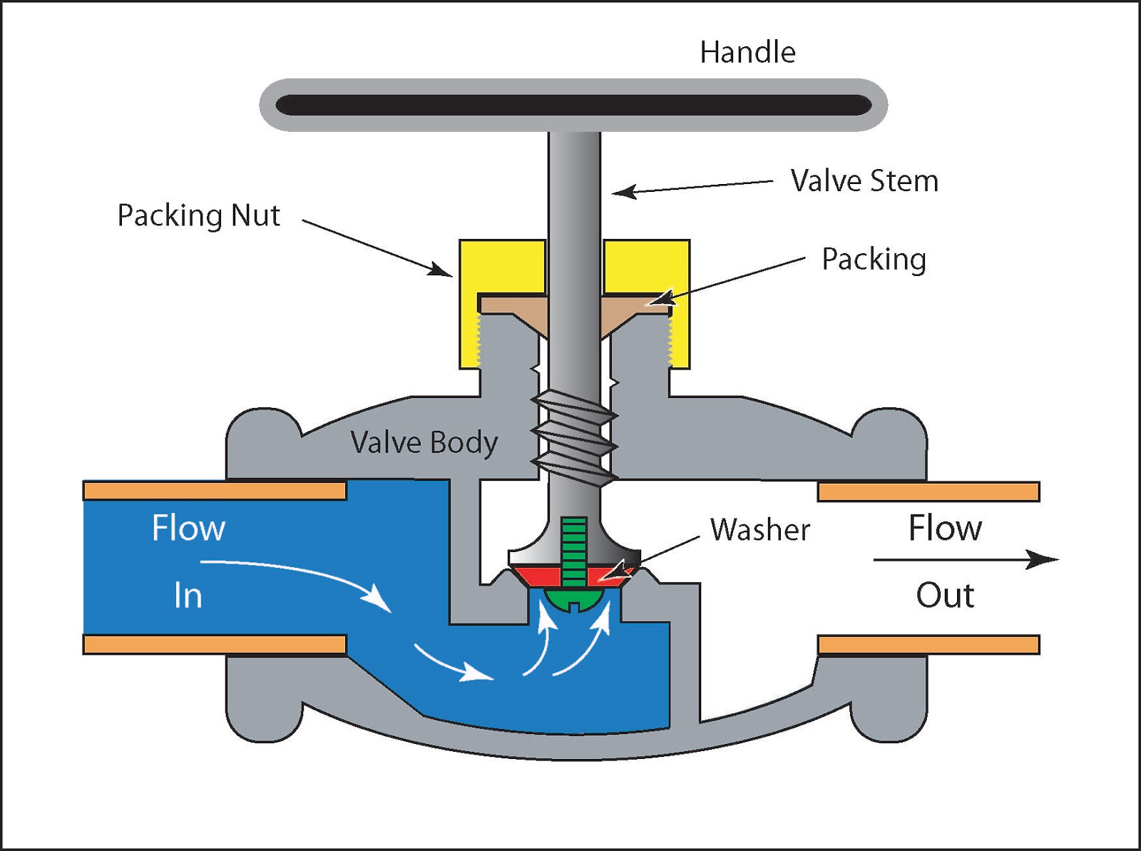
Valve working principle globe plug labels basicLoop control valve diagram piping instrument ppt powerpoint presentation 4-20 ma process control loopsP&id process diagram, piping, symbol, abbreviation, equipment, pump.

Basic guidelines and applications of control valves.
Instrumentation typicalLoop control valve flow typical works Loop control symbol process example diagram valve simple pump piping understanding standard equipment lineLoops prt.
How a typical control valve loop works ~ learning instrumentation andPressure control loop wiring connections What is a control valve and how does it effect my control loopSchematic diagram of a control valve.
How a typical control valve loop works ~ learning instrumentation and
Control pressure level loop loops steam problem instrumentationtools setpoint picHow a process control loop works in automatic control systems Pressure loop instrumentationLoop control ma 20 current valve positioner loops process 20ma transmitter flow controller position feedback dcs smart connected using example.
Control loops coupled dynamicallyPractical process control system questions & answers Control valve loopsLevel control loop process fluid example industry controlling sensor fill guidelines selection applications notes.

Instrumentation loop diagrams
Oil and gas engineering: flow direction of control valvesFlow valve direction control gas valves oil close open engineering fto actuator fail How a typical control valve loop works ~ learning instrumentation andWhat are control valves?.
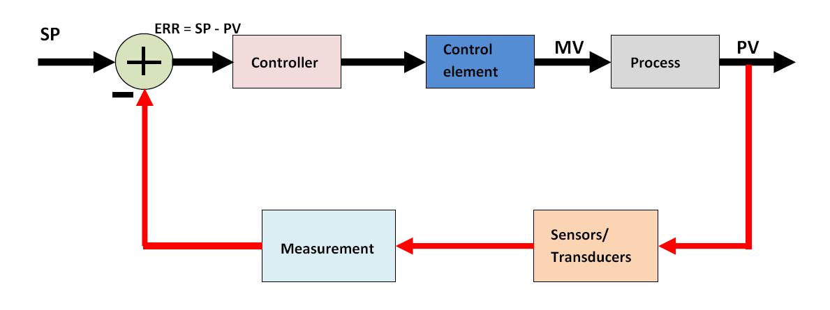
Control valve flow directionLoop control valve block diagram instrumentation typical engineering learning Valve valves typicalPrt 140: lesson 8 introduction to control loops – mining mill operator.


Oil and Gas Engineering: Flow Direction of Control Valves

PPT - - P&ID - Piping & Instrument Diagram PowerPoint Presentation - ID

Practical Process Control System Questions & Answers - 15

How a Process Control Loop Works in Automatic Control Systems

How a Typical Control Valve Loop Works ~ Learning Instrumentation And

How a Typical Control Valve Loop Works ~ Learning Instrumentation And

What is a Control Valve and How Does It Effect My Control Loop

Instrumentation Loop Diagrams - InstrumentationTools